Intellivision 2 Composite Video Install
The Step-by-Step Guide to install the Intellivision Composite Video Out Modification
(Click on the image to view a higher resolution of it)
1. Make sure that you have your Intv2 and modification board and a well lit work area. You will require approximately 45 minutes to complete this modification. Cable length fits either Intv 1 and Intv 2 consoles. If the cables seem to be too long for your console and prevent the mod from fitting easily into it, cut them down to the size you need.
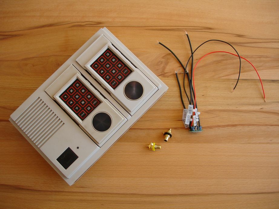
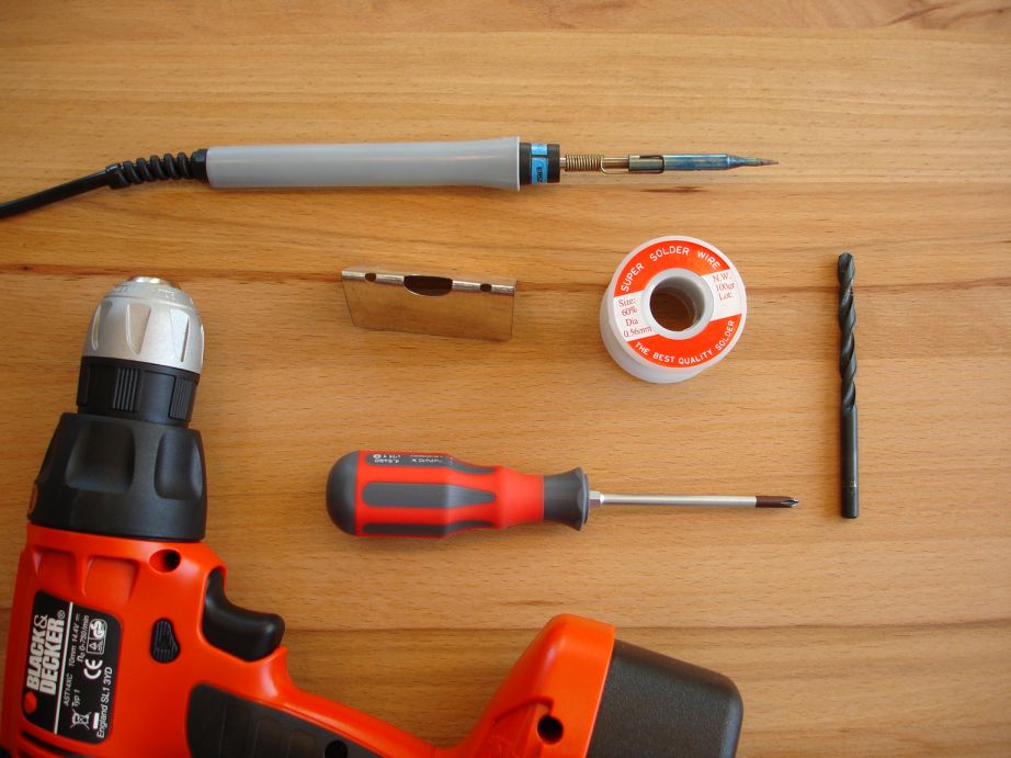
2. This I what you need:
a) A drill (to create the holes for the composite jacks)
b) A 8.0 drill bit (note: this is not a U.S.
measurement size)
c) A soldering iron
d) Solder wire
e) A Phillips screwdriver
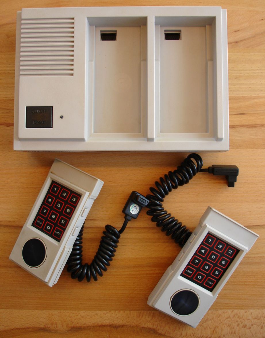
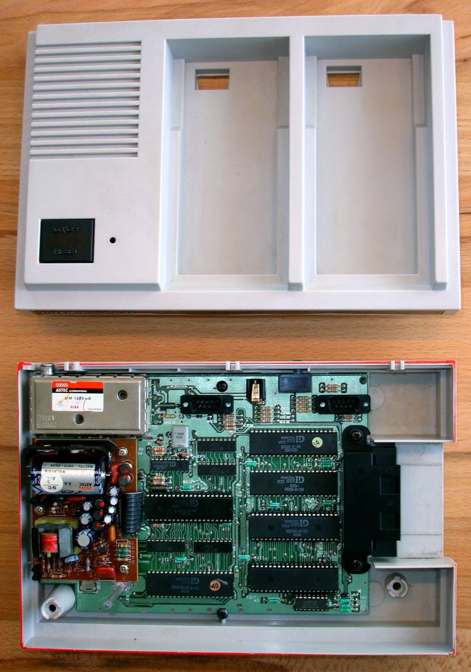
3. Detach the controllers.
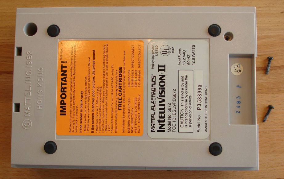
4. Remove the screws on the bottom of the console.
5. Remove the
top half of the case. There are hinges that hold the rear together and detach
when the cover is angled back.
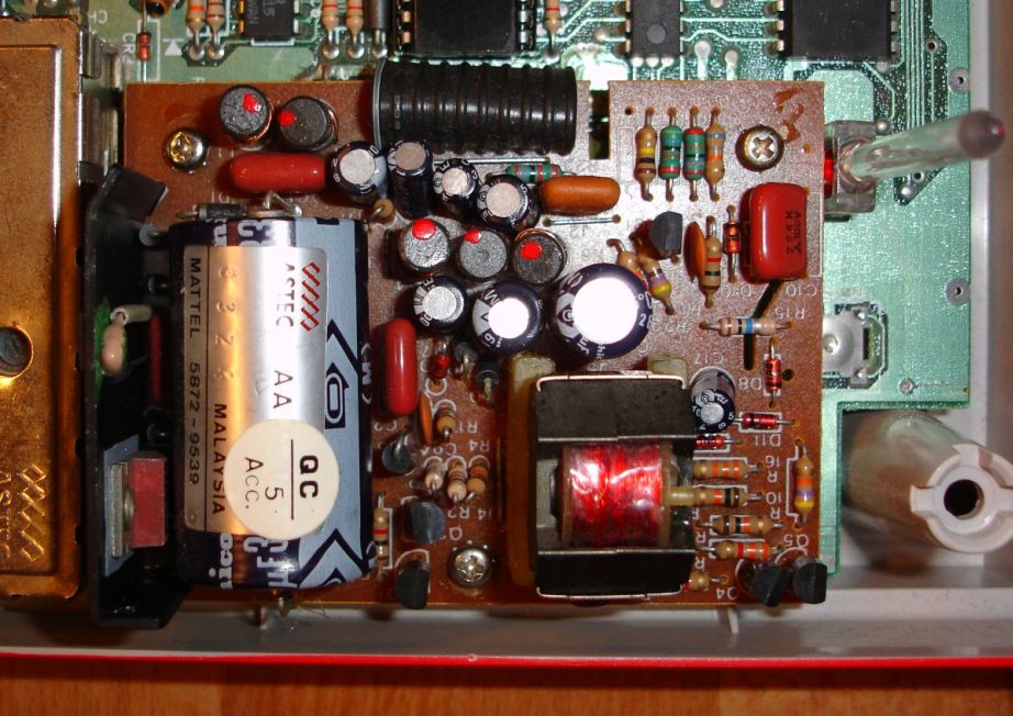
6. Locate the power
supply and unscrew all three screws. Turn the PCB upside down.
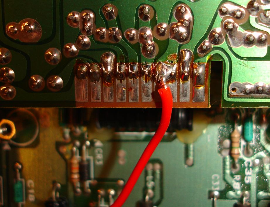
7. Solder the
red wire „+5V“ from the mod to the power supply PCB as shown in the picture. You
should attach the wire to the third soldering point to the left of the notch.
The correct soldering point is wider than the others.
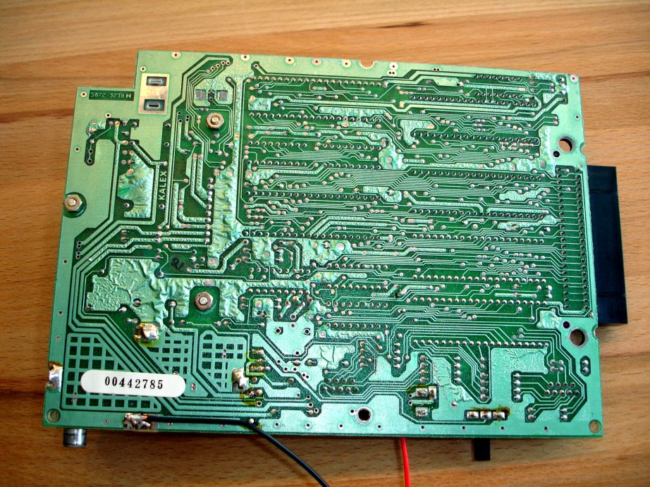
8.
Unscrew all four screws inside the Intellivision and take the PCB out. Turn it
upside down.
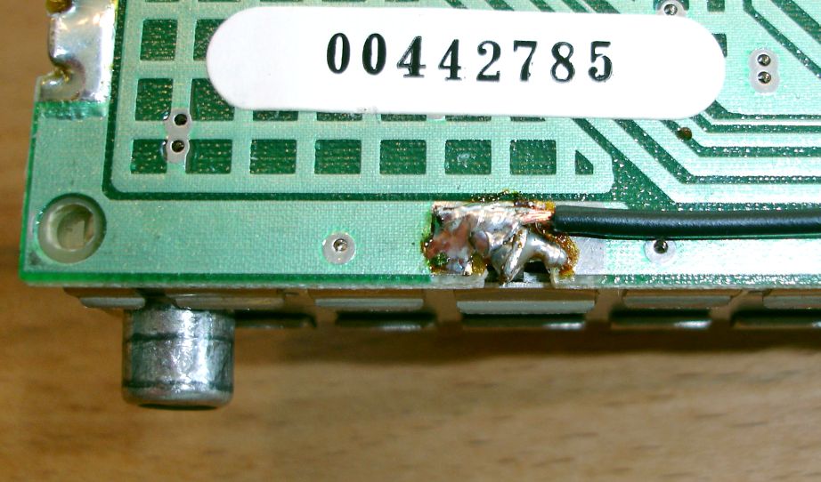
9.
Solder the black wire „GND“ from the mod to the backside of the PCB. Take care
to ensure that the wire is soldered to the correct position.
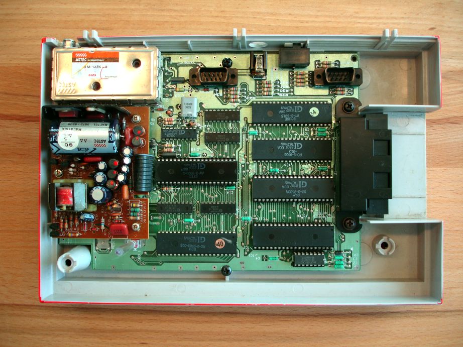
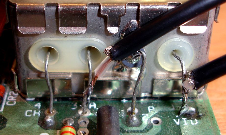
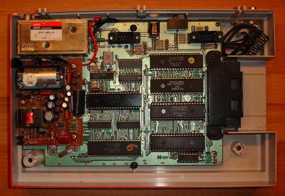
10. Solder the wire „V IN“ from the mod to the right wire of the RF modulator
as shown in the picture. Solder the „A IN“ wire from the mod to the second wire
from the left of the RF modulator.
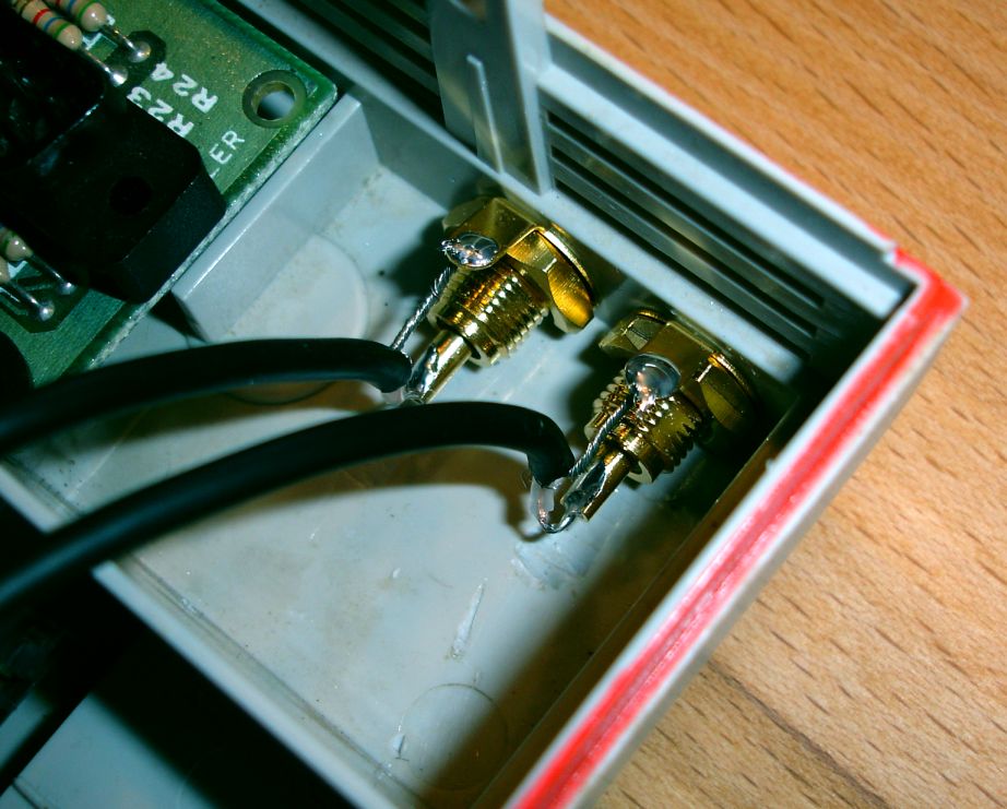
11. Drill two holes in the chassis for the RCA connectors.
12. Tighten the RCA socket locking nuts. Solder wire „V OUT“ to the yellow
RCA connector and „A OUT“ to the black RCA connector. Attach the wires as shown
in the picture.
13. Place the cables under the Intv PCB and put the the Intv PCB back inside
the chassis. Place the mod board in the open area next to the composite
connectors. Tighten the four screws that hold the Intv PCB down.
14. Return the cover by angling it so the two rear hinges engage. Close the
cover down gently and tighten the two screens. Attach the controllers.
Congratulations! You have completed installing the Intellivision Video
Modification.
The RF output will still be functional if you ever have the
need to use it.
** ALWAYS ** make sure you have the video wire connected to the YELLOW
composite jack. You could cause damage to your TV if you have the wires
reversed.
*** WARNING *** The holes needs to be precisely centered as there will be
little space remaining above and beneath the holes. Be sure to use an
appropriately sized drill. If you are unsure which size bit is correct, use a
smaller one first.
*** ATTENTION *** Attach the RCA connectors carefully.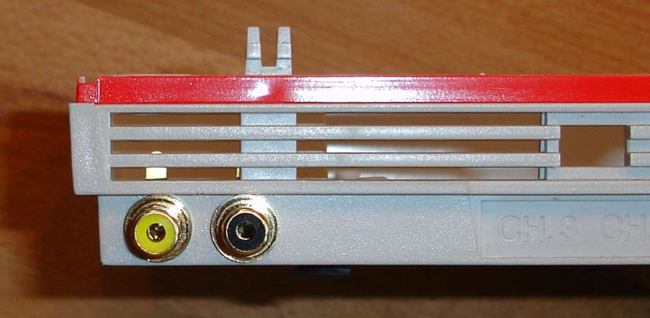
DISCLAIMER:
This mod has been carefully designed and manufactured. It has proven to work. To
my knowledge, it does not harm your system.
Nevertheless, I cannot be held responsible for any damage of your console (and
yourself), when you install it. You open and modify your Intellivision at your
own risk. Please make sure that your console is not connected to any power
source whenever the cover is removed.
Study all information given in this installation guide about how to install the
mod in the video game system carefully before you proceed. If there is anything
not absolutely clear to you about this process, do not install the mod.
-Oliver Puschatzki (October 2006)